00:00.0
00:06.0
Welcome to Part 6 on Mitsubishi FX PLC GX Works 2 tutorial.
00:07.5
00:13.2
In the previous tutorial (part 5) we have discussed the timers
00:13.3
00:21.0
of the Mitsubishi FX PLC and those were on delay timers.
00:22.5
00:30.0
There is an Off Delay type of timer but not available to some models of Mitsubishi PLC.
00:32.0
00:38.0
In this tutorial we will make a program so that we can have an Off Delay timer
00:38.1
00:41.6
using an On Delay timer.
00:43.4
00:47.5
Before that I will explain what is the difference between
00:47.6
00:50.5
On delay timer and Off delay timer.
00:52.5
01:00.4
In this timing chart we can see the difference between the two timers.
01:02.0
01:06.0
With on delay timer, when the drive input (X0) is closed,
01:07.0
01:13.0
the timer will start counting
01:13.1
01:18.0
until it reaches the specified set value.
01:18.1
01:25.0
When the counted value is equal to the set value, the timer contact turns on.
01:26.1
01:32.0
When the timer contact closes, the the output coil turns on.
01:35.3
01:52.0
As long as the drive input in On the timer remains On and so the output coil.
01:55.0
02:02.5
When the drive input is switched off, immediately the timer will turn off
02:02.6
02:06.0
and eventually the output coil Y0.
02:11.5
02:18.0
While on the off delay timer, when the drive input X0 is turned on
02:18.1
02:23.0
the output coil will also turn on.
02:23.1
02:35.0
While the drive input is on, the off delay timer will not start counting
02:35.1
02:39.7
and the output remains on.
02:41.0
02:55.0
When the drive input is switched off, the off delay timer will start counting
02:56.0
03:00.5
until it reaches the set value.
03:00.6
03:12.5
The output coil is then switched off.
03:12.6
03:21.5
Therefore there is a time delay to off the output after the input drive has been switched off.
03:26.1
03:35.0
Now we will create some programs that will function as an off delay timer.
06:49.1
06:58.8
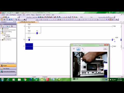
When input X1 is switched on, the output coil Y1 is turned on.
07:00.0
07:11.5
If input X1 is switched off timer T1 will start counting
07:12.5
07:17.2
but output coil will remain turned on because of the latched contact.
07:23.0
07:28.5
After input X1 has been switched off the timer starts counting.
07:29.0
07:32.9
While the output Y1 remains on.
07:34.1
07:40.5
When the count value reaches the set value equivalent to 20 seconds,
07:40.6
07:47.8
the normally closed timer contact will open and output Y1 will be turned off.
07:47.9
07:54.9
That is one example on how to program an off delay timer.
07:56.5
08:00.5
Now we will make another program for an off delay timer.
10:18.7
10:22.0
Now we will see the function of the new off delay program.
10:42.0
10:46.0
When input X2 is switched on, output Y2 is turned on.
10:53.5
10:58.0
If input X2 will be switched off, output Y2 should remain on.
10:58.1
11:02.9
and the timer will start counting.
11:21.5
11:25.5
When the counter value reaches the 20 seconds set value
11:25.6
11:30.7
output Y2 will turn off because normally closed timer contact will open.
11:32.8
11:39.0
Therefore we have an off delay on the output after the input has been switched off.
11:42.1
11:48.6
We will make a third example program for an off delay timer.
11:53.5
12:01.5
This time we will use a Set and Reset instruction.
14:39.4
14:46.0
When input X4 is switched on, output Y4 is set.
14:56.5
15:05.4
If input X4 is switched off, the timer will start counting
15:07.1
15:14.1
but output Y4 will remain on due to the Set instruction.
15:16.5
15:24.1
When the timer set value is reached the timer contact will close.
15:24.6
15:29.0
Output Y4 will then be reset.
15:32.7
15:35.3
Now we will switch off input X4.
15:37.5
15:40.2
The timer starts counting.
15:41.1
15:45.7
When the set value of 20 seconds is reached,
15:45.8
15:49.0
this timer contact will close to reset Y4.
16:07.3
16:16.1
Those are the examples on how to make an off delay timer
16:16.2
16:25.8
since some FX PLCs like the FX1S, FX1N and FX3G don't have it.
16:27.5
16:35.2
On the next video tutorial we will be discussing about counters.
16:37.1
16:42.0
Thank you for watching.