00:00.7
00:05.9
Welcome to Part 5 of our Mitsubishi GX Works 2 tutorial.
00:07.1
00:10.8
We are going to discuss about Timers.
00:10.9
00:17.4
The Mitsubushi FX PLC timer operates by counting
00:17.5
00:26.8
clock pulses in 1 millisecond, 10 milliseconds or 100 milliseconds resolution.
00:29.6
00:34.6
The timer device identifier is 'T'.
00:34.7
00:41.8
It is a bit device with 0 (off) or 1 (on) output
00:41.9
00:45.3
and the device address format is Decimal.
00:46.5
00:55.8
The addressing of Timer is not the same as the X and Y devices
00:55.9
00:58.7
which are limited to 0 to 7 or octal numbering system.
00:59.0
01:10.7
The timers can be addressed from 0 to 9 decimal numbers.
01:10.9
01:18.8
For example T0, T10, T11, T19, T20 and so on.
01:22.7
01:34.0
The type of timer that we can use depends on the PLC type.
01:35.5
01:46.7
For example, the FX1S PLC has normal timers only.
01:46.8
01:49.1
It doesn't have retentive timers.
01:49.2
02:01.3
The number of 100 ms timer for FX1S is only 63.
02:02.1
02:09.5
It starts from T0 to T62.
02:11.6
02:21.6
It has only 1 timer for the 1 ms resolution and it is T63.
02:23.3
02:37.6
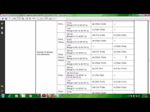
For the FX1N PLC there are 200 numbers of 100 ms normal timer from T0 to T199
02:38.9
02:51.2
and there 6 numbers 100 ms retentive timers from T250 to T255.
02:53.0
03:13.5
Retentive timers retains its present value even if the plc is stopped or there is a power failure.
03:14.5
03:23.2
Once the plc is run again or the power is back, and the driving contact is closed
03:23.3
03:30.7
the retentive will continue its counting from where it left off.
03:32.7
03:44.1
Therefore the type of timer depends on the PLC type.
03:48.6
03:56.9
This is how a timer program for an FX PLC is written.
04:03.0
04:11.9
A drive input contact is needed to activate the timer.
04:13.1
04:19.2
The timer uses an output coil symbol
04:19.3
04:27.4
Press function key F7 or click the Coil symbol from the tool bar.
04:27.5
04:48.0
Then enter the timer number, space and the constant K followed by the preset value.
04:48.1
05:15.4
This is how timer preset value is computed.
05:15.5
05:33.2
For a 10 seconds preset value with a 100ms timer resolution,
05:33.3
05:46.8
looking at the FX1N timer device table, for 100 ms resolution, the available timer is from T0 to T199.
05:53.9
06:07.0
Preset value in milliseconds divided by timer resolution.
06:07.1
06:30.0
Converting 10 seconds to milliseconds equals to 10,000 milliseconds
06:30.1
06:34.8
then divide by 100 milliseconds equals to 100.
06:34.9
06:47.7
Therefor a 10 seconds preset value is equivalent to 100 K constant.
06:48.2
07:13.0
We will add a timer contact to activate an output coil.
07:13.1
07:23.5
Compile the program then we will simulate.
07:26.0
07:36.0
We will close this contact.
07:37.0
07:40.5
We can see that the timer starts counting.
07:40.6
07:45.2
If we switch off the input contact the counted value goes back to 0.
07:45.3
07:49.4
That is because this timer is normal timer and not a retentive type.
07:49.5
07:52.4
We switch on again the drive contact.
07:55.0
08:00.6
When the preset value of 10 seconds is reached,the timer contact will close.
08:05.6
08:17.7
To open the timer contact and reset the timer the drive contact must be opened.
08:22.1
08:28.6
That is how a normal Mitsubishi FX PLC timer works.
08:31.0
08:36.3
There is also a retentive timer.
08:36.4
08:45.1
This different from normal timer has the ability to retain
08:45.2
08:56.6
the currently reached present value even after the drive contact has been removed.
09:01.0
09:08.2
These are the retentive timers and these are the addresses.
09:08.3
09:14.1
For FX1N, from T250 to T255.
09:17.4
09:32.8
For FX3S from T131 to T137 for 100ms resolution.
09:36.0
09:47.5
For FX3G 1ms resolution, from T246 to T249,
09:47.6
09:58.0
the same as for FX2N.
09:59.0
10:06.5
So the retentive timer depends on the PLC type except for FX1S
10:08.0
10:15.1
Let us make an example for retentive timer.
10:42.8
10:56.2
For example we need a 15 seconds timer, the constant should be 150.
11:54.5
12:08.1
If we open the drive contact the counted value is retained.
12:08.2
12:10.5
It did not reset to 0.
12:12.0
12:20.1
When we switch on again the drive input X1, the counting continues.
12:21.0
12:27.0
When it reaches the preset constant value of 150
12:27.1
12:33.2
its contact will close and the output coil will be activated.
12:33.3
12:39.0
Even if the drive contact will be switched off
12:40.5
12:49.4
The timer is not reset.
12:49.5
13:00.5
For retentive timers a reset instruction is needed.
14:05.0
14:22.8
We simulate again this retentive timer.
14:22.9
14:31.0
Switch off the drive input. The counted value is retained.
14:31.8
14:38.7
We need to close this contact to activate the Reset instruction.
14:56.3
15:02.2
We can see that the retentive timer has been reset and its contact is also opened.
15:06.8
15:19.5
That is all for now for the basics of Mitsubishi FX PLC timers.
15:21.0
15:27.9
For the next tutorial we will be discussing how to implement an Off delay timer on FX PLC.
15:28.0
15:38.5
FX PLCs don't have built in off delay timers
15:38.6
15:59.0
so we will make a small program using an ordinary timer.